5. The Autotransformer
5. The Autotransformer

Unlike the previous voltage transformer which has two electrically isolated windings called: the primary and the secondary, an Autotransformer has only one single voltage winding which is common to both sides. This single winding is “tapped” at various points along its length to provide a percentage of the primary voltage supply across its secondary load. Then the autotransformer has the usual magnetic core but only has one winding, which is common to both the primary and secondary circuits.
Therefore, in an autotransformer the primary and secondary windings are linked together both electrically and magnetically. The main advantage of this type of transformer design is that it can be made a lot cheaper for the same VA rating, but the biggest disadvantage of an autotransformer is that it does not have the primary/secondary winding isolation of a conventional double wound transformer.
The section of winding designated as the primary part of the winding is connected to the AC power source with the secondary being part of this primary winding. An autotransformer can also be used to step the supply voltage up or down by reversing the connections. If the primary is the total winding and is connected to a supply, and the secondary circuit is connected across only a portion of the winding, then the secondary voltage is “stepped-down” as shown.
Autotransformer Design
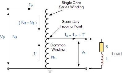
When the primary current IP is flowing through the single winding in the direction of the arrow as shown, the secondary current, IS, flows in the opposite direction. Therefore, in the portion of the winding that generates the secondary voltage, VS the current flowing out of the winding is the difference of IP and IS.
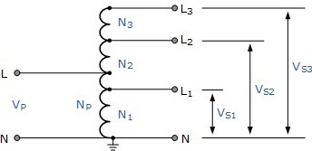
The Autotransformer can also be constructed with more than one single tapping point. Autotransformers can be used to provide different voltage points along its winding or increase its supply voltage with respect to its supply voltage VP as shown.
Autotransformer with Multiple Tapping Points
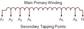
The standard method for marking an auto-transformer winding is to label it with capital (upper case) letters. So for example, A, B, Z etc. to identify the supply end. Generally, the common neutral connection is marked as N or n. For the secondary tapping’s, suffix numbers are used for all tapping points along the auto-transformers primary winding. These numbers generally start at number “1” and continue in ascending order for all tapping points as shown.
Autotransformer Terminal Markings
An autotransformer is used mainly for the adjustments of line voltages to either change its value or to keep it constant. If the voltage adjustment is by a small amount, either up or down, then the transformer ratio is small as VP and VS are nearly equal. Currents IP and IS are also nearly equal.
Therefore, the portion of the winding which carries the difference between the two currents can be made from a much smaller conductor size, since the currents are much smaller saving on the cost of an equivalent double wound transformer.
However, the regulation, leakage inductance and physical size (since there is no second winding) of an autotransformer for a given VA or KVA rating are less than for a double wound transformer.
Autotransformer’s are clearly much cheaper than conventional double wound transformers of the same VA rating. When deciding upon using an autotransformer it is usual to compare its cost with that of an equivalent double wound type.
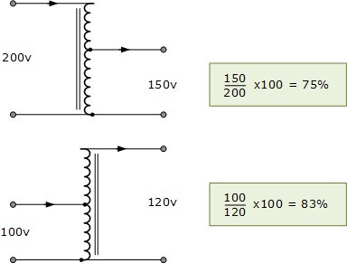
This is done by comparing the amount of copper saved in the winding. If the ratio “n” is defined as the ratio of the lower voltage to the higher voltage, then it can be shown that the saving in copper is: n*100%. For example, the saving in copper for the two autotransformers would be:
Autotransformer Example No1
An autotransformer is required to step-up a voltage from 220 volts to 250 volts. The total number of coil’s turns on the transformer main winding is 2000. Determine the position of the primary tapping point, the primary and secondary currents when the output is rated at 10KVA and the economy of copper saved.
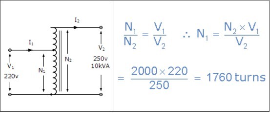
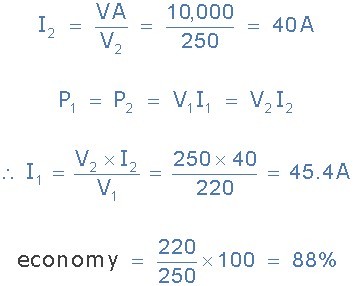
Thus, the primary current is 45.4 amperes, the secondary current drawn by the load is 40 amperes and 5.4 amperes flows through the common winding. The economy of copper is 88%.
Disadvantages of an Autotransformer
· The main disadvantage of an autotransformer is that it does not have the primary to secondary winding isolation of a conventional double wound transformer. Then an autotransformer cannot safely be used for stepping down higher voltages to much lower voltages suitable for smaller loads.
· If the secondary side winding becomes open-circuited, load current stops flowing through the primary winding stopping the transformer action resulting in the full primary voltage being applied to the secondary terminals.
· If the secondary circuit suffers a short-circuit condition, the resulting primary current would be much larger than an equivalent double wound transformer due to the increased flux linkage damaging the autotransformer.
· Since the neutral connection is common to both the primary and secondary windings, earthing of the secondary winding automatically Earth’s the primary as there is no isolation between the two windings. Double wound transformers are sometimes used to isolate equipment from earth.
The autotransformer has many uses and applications including the starting of induction motors, used to regulate the voltage of transmission lines, and can be used to transform voltages when the primary to secondary ratio is close to unity.
An autotransformer can also be made from conventional two-winding transformers by connecting the primary and secondary windings together in series and depending upon how the connection is made, the secondary voltage may add to, or subtract from, the primary voltage.
The Variable Autotransformer
As well as having a fixed or tapped secondary that produces a voltage output at a specific level, there is another useful application of the auto transformer type of arrangement which can be used to produce a variable AC voltage from a fixed voltage AC supply. This type of Variable Autotransformer is generally used in laboratories and science labs in schools and colleges and is known more commonly as the Variac.
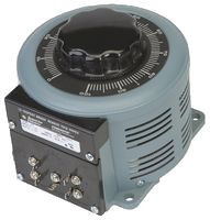
The construction of a variable autotransformer, or variac, is the same as for the fixed type. A single primary winding wrapped around a laminated magnetic core is used as in the auto transformer but instead of being fixed at some predetermined tapping point, the secondary voltage is tapped through a carbon brush.
This carbon brush is rotated or allowed to slide along an exposed section of the primary winding, making contact with it as it moves supplying the required voltage level.
Then a variable autotransformer contains a variable tap in the form of a carbon brush that slides up and down the primary winding which controls the secondary winding length and hence the secondary output voltage is fully variable from the primary supply voltage value to zero volts.
The variable autotransformer is usually designed with a significant number of primary windings to produce a secondary voltage which can be adjusted from a few volts to fractions of a volt per turn. This is achieved because the carbon brush or slider is always in contact with one or more turns of the primary winding. As the primary coil turns are evenly spaced along its length. Then the output voltage becomes proportional to the angular rotation.
Variable Autotransformer
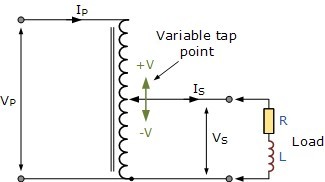
We can see that the variac can adjust the voltage to the load smoothly from zero to the rated supply voltage. If the supply voltage was tapped at some point along the primary winding, then potentially the output secondary voltage could be higher than the actual supply voltage. Variable autotransformer’s can also be used for the dimming of lights and when used in this type of application, they are sometimes called “dimmerstats”.
Variacs are also very useful in electrical and electronics workshops and labs as they can be used to provide a variable AC supply. But caution needs to be taken with suitable fuse protection to ensure that the higher supply voltage is not present at the secondary terminals under fault conditions.
The Autotransformer have many advantages over conventional double wound transformers. They are generally more efficient for the same VA rating, are smaller in size, and as they require less copper in their construction, their cost is less compared to double wound transformers of the same VA rating. Also, their core and copper losses, I2R are lower due to less resistance and leakage reactance giving a superior voltage regulation than the equivalent two winding transformer.
In the next tutorial about Transformers we will look at another design of transformer which does not have a conventional primary winding wound around its core. This type of transformer is commonly called a Current Transformer and is used to supply ammeters and other such electrical power indicators.
References
This article is reprinted from Electronics Tutorials - The Autotransformer.