2. Transformer Construction
2. Transformer Construction
This magnetic circuit, know more commonly as the “transformer core” is designed to provide a path for the magnetic field to flow around, which is necessary for induction of the voltage between the two windings.
However, this type of transformer construction where the two windings are wound on separate limbs is not very efficient since the primary and secondary windings are well separated from each other. This results in a low magnetic coupling between the two windings as well as large amounts of magnetic flux leakage from the transformer itself. But as well as this “O” shapes construction, there are different types of “transformer construction” and designs available which are used to overcome these inefficiencies producing a smaller more compact transformer.
The efficiency of a simple transformer construction can be improved by bringing the two windings within close contact with each other thereby improving the magnetic coupling. Increasing and concentrating the magnetic circuit around the coils may improve the magnetic coupling between the two windings, but it also has the effect of increasing the magnetic losses of the transformer core.
As well as providing a low reluctance path for the magnetic field, the core is designed to prevent circulating electric currents within the iron core itself. Circulating currents, called “eddy currents”, cause heating and energy losses within the core decreasing the transformers efficiency.
These losses are due mainly to voltages induced in the iron circuit, which is constantly being subjected to the alternating magnetic fields setup by the external sinusoidal supply voltage. One way to reduce these unwanted power losses is to construct the transformer core from thin steel laminations.
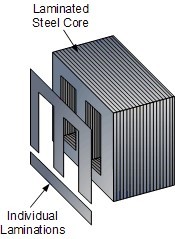
In all types of transformer construction, the central iron core is constructed from of a highly permeable material made from thin silicon steel laminations. These thin laminations are assembled together to provide the required magnetic path with the minimum of magnetic losses. The resistivity of the steel sheet itself is high, thus reducing any eddy current loss by making the laminations very thin.
These steel transformer laminations vary in thickness’s from between 0.25mm to 0.5mm and as steel is a conductor, the laminations and any fixing studs, rivets or bolts are electrically insulated from each other by a very thin coating of insulating varnish or by the use of an oxide layer on the surface.
Transformer Construction of the Core
Generally, the name associated with the construction of a transformer is dependent upon how the primary and secondary windings are wound around the central laminated steel core. The two most common and basic designs of transformer construction are the Closed-core Transformer and the Shell-core Transformer.
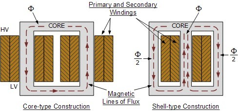
In the “closed-core” type (core form) transformer, the primary and secondary windings are wound outside and surround the core ring. In the “shell type” (shell form) transformer, the primary and secondary windings pass inside the steel magnetic circuit (core) which forms a shell around the windings as shown below.
Transformer Core Construction

In both types of transformer core design, the magnetic flux linking the primary and secondary windings travels entirely within the core with no loss of magnetic flux through air. In the core type transformer construction, one half of each winding is wrapped around each leg (or limb) of the transformers magnetic circuit as shown above.
The coils are not arranged with the primary winding on one leg and the secondary on the other but instead half of the primary winding and half of the secondary winding are placed one over the other concentrically on each leg in order to increase magnetic coupling allowing practically all of the magnetic lines of force go through both the primary and secondary windings at the same time. However, with this type of transformer construction, a small percentage of the magnetic lines of force flow outside of the core, and this is called “leakage flux”.
Shell type transformer cores overcome this leakage flux as both the primary and secondary windings are wound on the same center leg or limb which has twice the cross-sectional area of the two outer limbs. The advantage here is that the magnetic flux has two closed magnetic paths to flow around external to the coils on both left and right hand sides before returning back to the central coils.
This means that the magnetic flux circulating around the outer limbs of this type of transformer construction is equal to Φ/2. As the magnetic flux has a closed path around the coils, this has the advantage of decreasing core losses and increasing overall efficiency.
Transformer Laminations
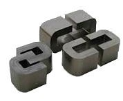
But you may be wondering as to how the primary and secondary windings are wound around these laminated iron or steel cores for these types of transformer constructions. The coils are firstly wound on a former which has a cylindrical, rectangular or oval type cross section to suit the construction of the laminated core. In both the shell and core type transformer constructions, in order to mount the coil windings, the individual laminations are stamped or punched out from larger steel sheets and formed into strips of thin steel resembling the letters “E”s, “L”s, “U”s and “I”s as shown below.
Transformer Core Types
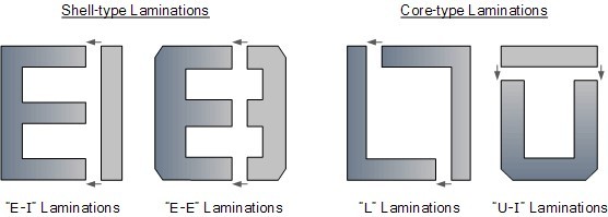
These lamination stampings when connected together form the required core shape. For example, two “E” stampings plus two end closing “I” stampings to give an E-I core forming one element of a standard shell-type transformer core. These individual laminations are tightly butted together during the transformers construction to reduce the reluctance of the air gap at the joints producing a highly saturated magnetic flux density.
Transformer core laminations are usually stacked alternately to each other to produce an overlapping joint with more lamination pairs being added to make up the correct core thickness. This alternate stacking of the laminations also gives the transformer the advantage of reduced flux leakage and iron losses. E-I core laminated transformer construction is mostly used in isolation transformers, step-up and step-down transformers as well as auto transformers.
Transformer Winding Arrangements
Transformer windings form another important part of a transformer construction, because they are the main current-carrying conductors wound around the laminated sections of the core. In a single-phase two winding transformer, two windings would be present as shown. The one which is connected to the voltage source and creates the magnetic flux called the primary winding, and the second winding called the secondary in which a voltage is induced as a result of mutual induction.
If the secondary output voltage is less than that of the primary input voltage the transformer is known as a “Step-down Transformer”. If the secondary output voltage is greater than the primary input voltage it is called a “Step-up Transformer”.
Core-type Construction
The type of wire used as the main current carrying conductor in a transformer winding is either copper or aluminum. While aluminum wire is lighter and generally less expensive than copper wire, a larger cross sectional area of conductor must be used to carry the same amount of current as with copper so it is used mainly in larger power transformer applications.
Small kVA power and voltage transformers used in low voltage electrical and electronic circuits tend to use copper conductors as these have a higher mechanical strength and smaller conductor size than equivalent aluminum types. The downside is that when complete with their core, these transformers are much heavier.
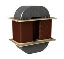
Transformer windings and coils can be broadly classified into concentric coils and sandwiched coils. In core-type transformer construction, the windings are usually arranged concentrically around the core limb as shown above with the higher voltage primary winding being wound over the lower voltage secondary winding.
Sandwiched or “pancake” coils consist of flat conductors wound in a spiral form and are so named due to the arrangement of conductors into discs. Alternate discs are made to spiral from outside towards the center in an interleaved arrangement with individual coils being stacked together and separated by insulating materials such as paper of plastic sheet. Sandwich coils and windings are more common with shell type core construction.
Helical Windings also known as screw windings are another very common cylindrical coil arrangement used in low voltage high current transformer applications. The windings are made up of large cross sectional rectangular conductors wound on its side with the insulated strands wound in parallel continuously along the length of the cylinder, with suitable spacers inserted between adjacent turns or discs to minimize circulating currents between the parallel strands. The coil progresses outwards as a helix resembling that of a corkscrew.
Transformer Core
The insulation used to prevent the conductors shorting together in a transformer is usually a thin layer of varnish or enamel in air cooled transformers. This thin varnish or enamel paint is painted onto the wire before it is wound around the core.
In larger power and distribution transformers the conductors are insulated from each other using oil impregnated paper or cloth. The whole core and windings are immersed and sealed in a protective tank containing transformer oil. The transformer oil acts as an insulator and also as a coolant.
Transformer Dot Orientation
We cannot just simply take a laminated core and wrap one of the coil configurations around it. We could but we may find that the secondary voltage and current may be out-of-phase with that of the primary voltage and current. The two coil windings do have a distinct orientation of one with respect to the other. Either coil could be wound around the core clockwise or anticlockwise so to keep track of their relative orientation’s “dots” are used to identify a given end of each winding.
This method of identifying the orientation or direction of a transformers windings is called the “dot convention”. Then a transformers windings are wound so that the correct phase relations exist between the winding voltages with the transformers polarity being defined as the relative polarity of the secondary voltage with respect to the primary voltage as shown below.
Transformer Construction using Dot Orientation
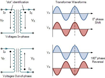
The first transformer shows its two “dots” side by side on the two windings. The current leaving the secondary dot is “in-phase” with the current entering the primary side dot. Thus the polarities of the voltages at the dotted ends are also in-phase so when the voltage is positive at the dotted end of the primary coil, the voltage across the secondary coil is also positive at the dotted end.
The second transformer shows the two dots at opposite ends of the windings which means that the transformers primary and secondary coil windings are wound in opposite directions. The result of this is that the current leaving the secondary dot is 180o “out-of-phase” with the current entering the primary dot. So the polarities of the voltages at the dotted ends are also out-of-phase so when the voltage is positive at the dotted end of the primary coil, the voltage across the corresponding secondary coil will be negative.
Then the construction of a transformer can be such that the secondary voltage may be either “in-phase” or “out-of-phase” with respect to the primary voltage. In transformers which have a number of different secondary windings, each of which is electrically isolated from each other it is important to know the dot polarity of the secondary windings so that they can be connected together in series-aiding (secondary voltage is summed) or series-opposing (the secondary voltage is the difference) configurations.
The ability to adjust the turns ratio of a transformer is often desirable to compensate for the effects of variations in the primary supply voltage, the regulation of the transformer or varying load conditions. Voltage control of the transformer is generally performed by changing the turns ratio and therefore its voltage ratio whereby a part of the primary winding on the high voltage side is tapped out allowing for easy adjustment. The tapping is preferred on the high voltage side as the volts per turn are lower than the low voltage secondary side.
Transformer Primary Tap Changes
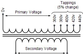
In this simple example, the primary tap changes are calculated for a supply voltage change of ±5%, but any value can be chosen. Some transformers may have two or more primary or two or more secondary windings for use in different applications providing different voltages from a single core.
Transformer Core Losses
The ability of iron or steel to carry magnetic flux is much greater than it is in air, and this ability to allow magnetic flux to flow is called permeability. Most transformer cores are constructed from low carbon steels which can have permeabilities in the order of 1500 compared with just 1.0 for air.
This means that a steel laminated core can carry a magnetic flux 1500 times better than that of air. However, when a magnetic flux flows in a transformers steel core, two types of losses occur in the steel. One termed “eddy current losses” and the other termed “hysteresis losses”.
Hysteresis Losses
Transformer Hysteresis Losses are caused because of the friction of the molecules against the flow of the magnetic lines of force required to magnetize the core, which are constantly changing in value and direction first in one direction and then the other due to the influence of the sinusoidal supply voltage.
This molecular friction causes heat to be developed which represents an energy loss to the transformer. Excessive heat loss can overtime shorten the life of the insulating materials used in the manufacture of the windings and structures. Therefore, cooling of a transformer is important.
Also, transformers are designed to operate at a particular supply frequency. Lowering the frequency of the supply will result in increased hysteresis and higher temperature in the iron core. So reducing the supply frequency from 60 Hertz to 50 Hertz will raise the amount of hysteresis present, decreased the VA capacity of the transformer.
Eddy Current Losses
Transformer Eddy Current Losses on the other hand are caused by the flow of circulating currents induced into the steel caused by the flow of the magnetic flux around the core. These circulating currents are generated because to the magnetic flux the core is acting like a single loop of wire. Since the iron core is a good conductor, the eddy currents induced by a solid iron core will be large.
Eddy currents do not contribute anything towards the usefulness of the transformer but instead they oppose the flow of the induced current by acting like a negative force generating resistive heating and power loss within the core.
Laminating the Iron Core
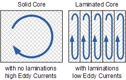
Eddy current losses within a transformer core can not be eliminated completely, but they can be greatly reduced and controlled by reducing the thickness of the steel core. Instead of having one big solid iron core as the magnetic core material of the transformer or coil, the magnetic path is split up into many thin pressed steel shapes called “laminations”.
The laminations used in a transformer construction are very thin strips of insulated metal joined together to produce a solid but laminated core as we saw above. These laminations are insulated from each other by a coat of varnish or paper to increase the effective resistivity of the core thereby increasing the overall resistance to limit the flow of the eddy currents.
The result of all this insulation is that the unwanted induced eddy current power-loss in the core is greatly reduced, and it is for this reason why the magnetic iron circuit of every transformer and other electro-magnetic machines are all laminated. Using laminations in a transformer construction reduces eddy current losses.
The losses of energy, which appears as heat due both to hysteresis and to eddy currents in the magnetic path, is known commonly as “transformer core losses”. Since these losses occur in all magnetic materials as a result of alternating magnetic fields. Transformer core losses are always present in a transformer whenever the primary is energized, even if no load is connected to the secondary winding. Also these hysteresis and the eddy current losses are sometimes referred to as “transformer iron losses”, as the magnetic flux causing these losses is constant at all loads.
Copper Losses
But there is also another type of energy loss associated with transformers called “copper losses”. Transformer Copper Losses are mainly due to the electrical resistance of the primary and secondary windings. Most transformer coils are made from copper wire which has resistance in Ohms, ( Ω ). This resistance opposes the magnetizing currents flowing through them.
When a load is connected to the transformers secondary winding, large electrical currents flow in both the primary and the secondary windings, electrical energy and power ( or the I2 R ) losses occur as heat. Generally copper losses vary with the load current, being almost zero at no-load, and at a maximum at full-load when current flow is at maximum.
A transformers VA rating can be increased by better design and transformer construction to reduce these core and copper losses. Transformers with high voltage and current ratings require conductors of large cross-section to help minimize their copper losses. Increasing the rate of heat dissipation (better cooling) by forced air or oil, or by improving the transformers insulation so that it will withstand higher temperatures can also increase a transformers VA rating.
Then we can define an ideal transformer as having:
· No Hysteresis loops or Hysteresis losses → 0
· Infinite Resistivity of core material giving zero Eddy current losses → 0
· Zero winding resistance giving zero I2*R copper losses → 0
In the next tutorial about Transformers we will look at Transformer Loading of the secondary winding with respect to an electrical load and see the effect a “NO-load” and a “ON-load” connected transformer has on the primary winding current.
References
This article is reprinted from Electronics Tutorials - Transformer Construction.