3. Transformer Loading
3. Transformer Loading
In the previous transformer tutorials, we have assumed that the transformer is ideal, that is one in which there are no core losses or copper losses in the transformer’s windings. However, in real world transformers there will always be losses associated with the transformers loading as the transformer is put “on-load”. But what do we mean by: Transformer Loading.
Well first let’s look at what happens to a transformer when it is in this “no-load” condition, that is with no electrical load connected to its secondary winding and therefore no secondary current flowing.
A transformer is said to be on “no-load” when its secondary side winding is open circuited, in other words, nothing is attached and the transformer loading is zero. When an AC sinusoidal supply is connected to the primary winding of a transformer, a small current, IOPEN will flow through the primary coil winding due to the presence of the primary supply voltage.
With the secondary circuit open, nothing connected, a back EMF along with the primary winding resistance acts to limit the flow of this primary current. Obviously, this no-load primary current ( Io ) must be sufficient to maintain enough magnetic field to produce the required back emf. Consider the circuit below.
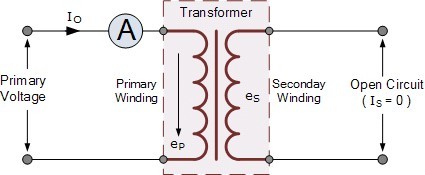
Transformer “No-load” Condition

The ammeter above will indicate a small current flowing through the primary winding even though the secondary circuit is open circuited. This no-load primary current is made up of the following two components:
· An in-phase current, IE which supplies the core losses (eddy current and hysteresis).
· A small current, IM at 90o to the voltage which sets up the magnetic flux.
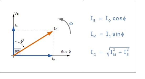
Note that this no-load primary current, Io is very small compared to the transformers normal full-load current. Also due to the iron losses present in the core as well as a small amount of copper losses in the primary winding, Io does not lag behind the supply voltage, Vp by exactly 90o, ( cosφ = 0 ), there will be some small phase angle difference.
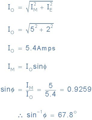
Transformer Loading Example No1
A single phase transformer has an energy component, IE of 2 Amps and a magnetizing component, IM of 5 Amps. Calculate the no-load current, Io and resulting power factor.
Transformer “On-load”
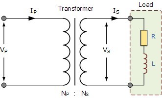
When an electrical load is connected to the secondary winding of a transformer and the transformer loading is therefore greater than zero, a current flows in the secondary winding and out to the load. This secondary current is due to the induced secondary voltage, set up by the magnetic flux created in the core from the primary current.
The secondary current, IS which is determined by the characteristics of the load, creates a self-induced secondary magnetic field, ΦS in the transformer core which flows in the exact opposite direction to the main primary field, ΦP. These two magnetic fields oppose each other resulting in a combined magnetic field of less magnetic strength than the single field produced by the primary winding alone when the secondary circuit was open circuited.
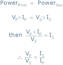
This combined magnetic field reduces the back EMF of the primary winding causing the primary current, IP to increase slightly. The primary current continues to increase until the cores magnetic field is back at its original strength, and for a transformer to operate correctly, a balanced condition must always exist between the primary and secondary magnetic fields. This results in the power to be balanced and the same on both the primary and secondary sides. Consider the circuit below.
Transformer “On-load”
We know that the turns ratio of a transformer states that the total induced voltage in each winding is proportional to the number of turns in that winding and also that the power output and power input of a transformer is equal to the volts times amperes, ( V x I ). Therefore:
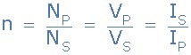
But we also know previously that the voltage ratio of a transformer is equal to the turns ratio of a transformer as: “voltage ratio = turns ratio”. Then the relationship between the voltage, current and number of turns in a transformer can be linked together and is therefore given as:
Transformer Ratio
· Where:
· NP/NS = VP/VS - represents the voltage ratio
· NP/NS = IS/IP - represents the current ratio
Note that the current is inversely proportional to both the voltage and the number of turns. This means that with a transformer loading on the secondary winding, in order to maintain a balanced power level across the transformers windings, if the voltage is stepped up, the current must be stepped down and vice versa. In other words, “higher voltage — lower current” or “lower voltage — higher current”.
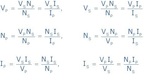
As a transformers ratio is the relationships between the number of turns in the primary and secondary, the voltage across each winding, and the current through the windings, we can rearrange the above transformer ratio equation to find the value of any unknown voltage, ( V ) current, ( I ) or number of turns, ( N ) as shown.
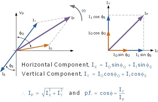
The total current drawn from the supply by the primary winding is the vector sum of the no-load current, Io and the additional supply current, I1 as a result of the secondary transformer loading and which lags behind the supply voltage by an angle of Φ. We can show this relationship as a phasor diagram.
Transformer Loading Current

If we are given currents, IS and Io, we can calculate the primary current, IP by the following methods.
Transformer Loading Example No2
A single phase transformer has 1000 turns on its primary winding and 200 turns on its secondary winding. The transformers “no-load” current taken from the supply is 3 Amps at a power factor of 0.2 lagging. Calculate the primary winding current, IP and its corresponding power factor, φ when the secondary current supplying a transformer loading is 280 Amperes at 0.8 lagging.
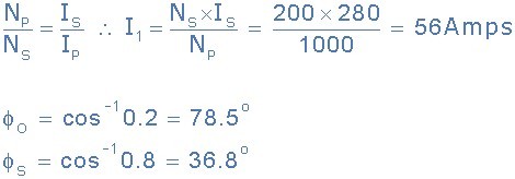
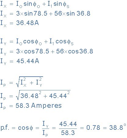
You may have noticed that the phase angle of the primary current, φP is very nearly the same as that of the secondary current phase angle, φS. This is due to the fact that the no-load current of 3 amperes is very small compared to the larger 56 amperes drawn by the primary winding from the supply.
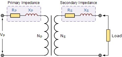
Actual real life, transformer windings have impedances of both XL and R. These impedances need to be taken into account when drawing the phasor diagrams as these internal impedances because voltage drops to occur within the transformers windings. The internal impedances are due to the resistance of the windings and an inductance drop called the leakage reactance resulting from the leakage flux. These internal impedances are given as:
So the primary and secondary windings of a transformer possess both resistance and reactance. Sometimes, it can be more convenient if all these impedances are on the same side of the transformer to make the calculations easier. It is possible to move the primary impedances to the secondary side or the secondary impedances to the primary side. The combined values of R and L impedances are called “Referred Impedances” or “Referred Values”. The object here is to group together the impedances within the transformer and have just one value of R and XL in our calculations as shown.
Combining Transformer Impedances
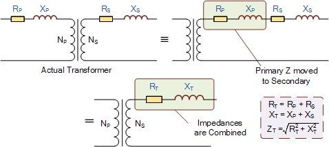
In order to move a resistance from one side of the transformer to the other, we must first multiply them by the square of the turns ratio, ( Turns Ratio2 ) in our calculations. So for example, to move a resistance of 2Ω from one side to the other in a transformer that has a turns ratio of 8:1 will have a new resistive value of: 2 x 82 = 128Ω.
Note that if you move a resistance from a higher voltage side the new resistance value will increase and if you move the resistance from a lower voltage side its new value will decrease. This applies to the load resistance and reactance as well.
Transformer Voltage Regulation
The voltage regulation of a transformer is defined as the change in secondary terminal voltage when the transformer loading is at its maximum, i.e. full-load applied while the primary supply voltage is held constant. Regulation determines the voltage drop (or increase) that occurs inside the transformer as the load voltage becomes too low as a result of the transformers loading being to high which therefore affects its performance and efficiency.
Voltage regulation is expressed as a percentage (or per unit) of the no-load voltage. Then if E represents the no-load secondary voltage and V represents the full-load secondary voltage, the percentage regulation of a transformer is given as:

So for example, a transformer delivers 100 volts at no-load and the voltage drops to 95 volts at full load, the regulation would be 5%. The value of E – V will depend upon the internal impedance of the winding which includes its resistance, R and more significantly its AC reactance X, the current and the phase angle.
Also voltage regulation generally increases as the power factor of the load becomes more lagging (inductive). Voltage regulation with regards to the transformer loading can be either positive or negative in value, that is with the no-load voltage as reference, the change down in regulation as the load is applied, or with the full-load as reference and the change up in regulation as the load is reduced or removed.
In general, the regulation of the core type transformer when the transformer loading is high is not as good as the shell type transformer. This is because the shell type transformer has better flux distribution due to the interlacing of the coil windings.
In the next tutorial about Transformers we will look at the Multiple Winding Transformer which has more than one primary winding or more than one secondary winding and see how we can connect two or more secondary windings together in order to supply more voltage or more current to the connected load.
References
This article is reprinted from Electronics Tutorials - Transformer Loading.